FPGA
We’ll be working in the verilog directory.
Setup
-
You will need Verilog setup from the previous step. Remember to also initialize the Git submodule with libraries:
git submodule update --init -
Then, install the Icestorm toolchain. The easiest way is using the apio project:
pip3 install --user apio
apio install icestorm
This will download and unpack the necessary software in your home directory (under
~/.apio). If you want to run the tools directly (not only from Makefile), add the toolchain to yourPATH, for instance in your.bashrc:export PATH="$HOME/.apio/packages/toolchain-icestorm/bin/:$PATH" -
Under Linux, add yourself to the
dialoutgroup so that you can connect to the chip without sudo: (TODO: This doesn’t seem to work for everyone, useUSE_SUDO=1)sudo adduser $USER dialoutYou will need to log out and log in again.
-
Now try uploading a design. Connect the Icestick board, and run:
make flash V=blinky_icestick.vIf for some reason you need sudo, append
USE_SUDO=1.If you encounter problems under Mac OS X, see Project IceStorm – Notes for Installing on OSX. You will probably need to unload Apple’s FTDI driver:
sudo kextunload com.apple.driver.AppleUSBFTDI -
For the TinyFPGA BX board, you need to additionally do the following:
pip3 install --user tinyprog
apio drivers --serial-enable
Building and flashing
To upload a design, use make flash. For example:
make flash V=blinky_icestick.v
For the TinyFPGA BX module, you need to set BOARD=bx flag:
make flash V=blinky_bx.v BOARD=bx
Same for the IceBreaker module:
make flash V=blinky_icebreaker.v BOARD=icebreaker
(Append USE_SUDO=1 if you need to use sudo).
The build process has the following steps:
- Logic synthesis, using
yosys. This produces a.bliffile with your design compiled down to components available on the FPGA chip (look-up tables, flip-flops, block RAMs, etc.) - Place and route, using
arachne-pnr. This produces.ascand then.binfiles containing the final chip configuration (a bitstream). - Programming the chip, using
iceprog/tinyprog. This uploads the.binto the chip over USB.
Pins
You can find the available pins in fpga-tools/pcf directory. Your module will need to reference these.
Here are the pinouts for reference:
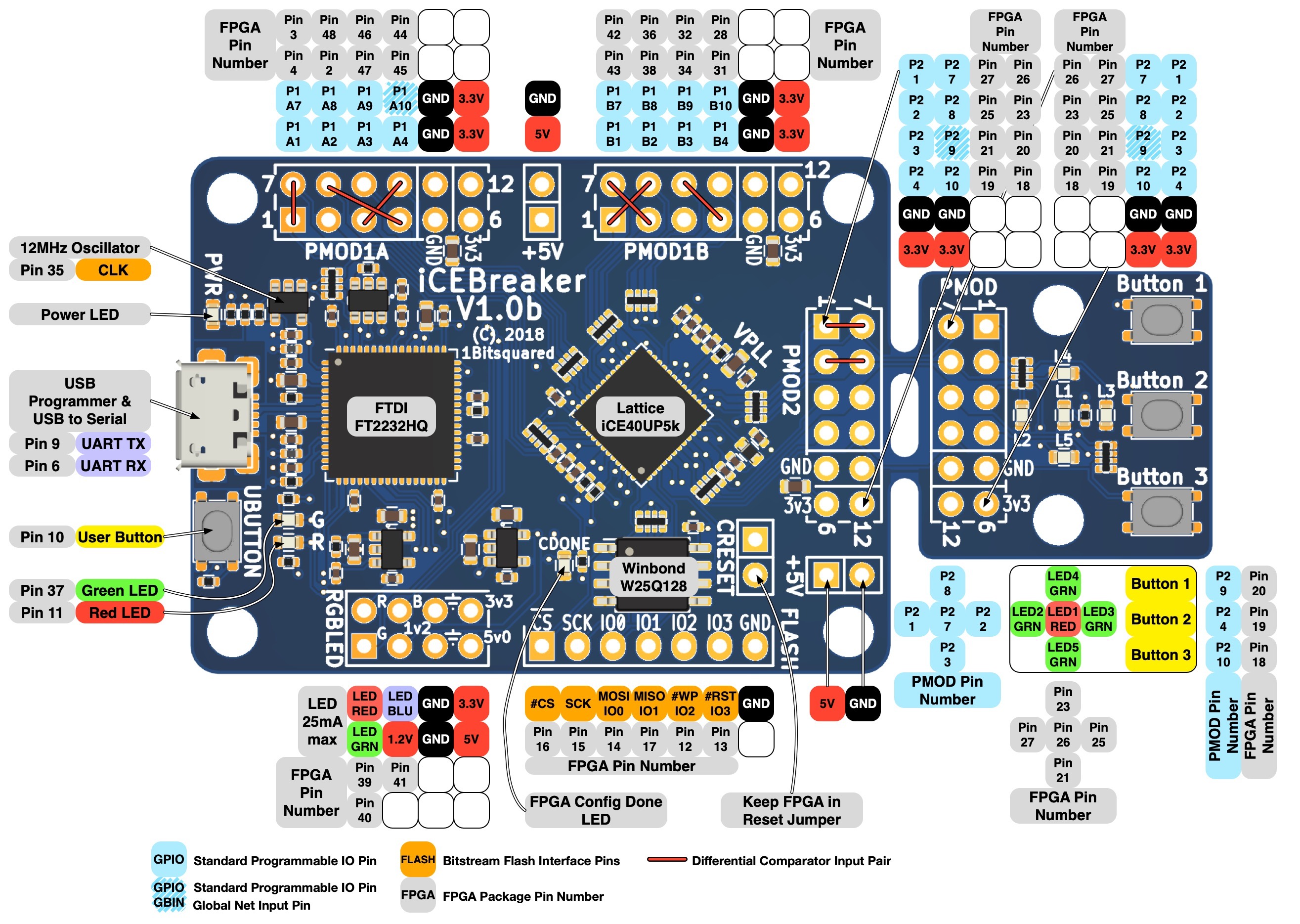
Ideas
Here is a list of ideas that you can implement. You will find some hints regarding different parts in the next section.
- Counter: Implement a counter that increases every second. The Icestick
has 5 LEDs, you can use them to show an increasing 5-bit number.
- Try connecting the segment display.
- Connect a button. Make the counter increase not with time, but every time the button is pressed. Add a reset button.
- Traffic lights: Implement the traffic lights example from the previous chapter. You will need three LEDs (don’t forget the resistors!) and a button.
- Fade LEDs in and out by implementing pulse-width modulation.
- Serial link: Use the chip to communicate with computer over the serial
link.
- Memory buffer: Implement a chip that has a small memory buffer and responds to “read” and “write” commands.
- Screens: Draw something on the screen. Create an animation. Send a
picture over the serial link and draw it.
- Pong game?
- Game of Life demo.
- Display text. Unscii 8x8 bitmap fonts might come in handy, you can download the fonts in a hex format which is basically a one byte, one row bitmap. And here is a font converted to column-by-column already.
Parts
Here are some parts you can use in your projects.
Clock
The Icestick has a 12 MHz clock signal, the BX a 16 MHz one. For changes that a
human can notice, you will need to divide it to create a slower clock. See the
blinky example.
It’s also possible to get a faster clock using a
PLL,
but I haven’t tried that yet. The icetime tool should tell you the maximum
frequency for your design (run make time). Use icepll to generate the
right parameters for the PLL module.
LEDs
The Icestick has 5 LEDs, the BX has one. You can turn them on and off just by specifying the pins in module output.
You can connect your own LEDs as well, just make sure to connect the right resistors. The voltage on pins is 3.3 V.
Buttons and switches
You will need a pull-down or pull-up resistor. See for instance the button example for Arduino.
You can also use a an internal pull-up from FPGA. See button.v on how to do
that.
Seven-segment display
Here is a spec sheet for the display. Ours has a common anode for all 4 digits. You will need to display the digits one at a time. Here is a blog post on multiplexing 7 segment display.
(TODO add more info once we try that)
Serial link (UART)
You can use the chip on Icestick to communicate with your computer over a
serial connection (exposed as a second USB device; visible under /dev/ttyUSB1
under Linux).
See uart_hello.v for a simple program that sends “Hello, world!”
repeatedly. You can use uart.py to receive the data. Here is the
documentation for pySerial
library. Remember to set
the baud rate correctly on both ends!
You can also use a serial terminal such as gtkterm (see for instance
Communicate with hardware using USB cable for
Ubuntu).
Note that the module we’re using, uart.v, is a third-party software
developed by Tim Goddard.
OLED displays
I have two OLED screens:
- “Two-color” (actually monochrome) 128x64 screen. The data is laid out in 8 rows of 128 bytes each. Each row describes a 128x8 strip, each byte is a 1x8 segment.
- 65536-color 96x64 screen. Each pixel is 16 bits. Note that this is more memory that Icestick has on board (12 KB; the Icestick’s block RAMs hold 8 KB total).
See oled_pattern.v and oled_pattern_color.v for details on how to use.
You might want to load some initial data into memory. You can use the
$readmemh
function to do
that.
Links
- open-fpga-verilog-tutorial - an excellent tutorial series, translated from Spanish
- ice40-examples
- migen - a circuit generator in Python
- Lattice iCE40 LP/HX Family Data Sheet
- fpga4fun - various project ideas: VGA, HDMI, SDRAM controller…
- Initializing memory in Verilog
- ICE40 layout viewer, renders your .asc file